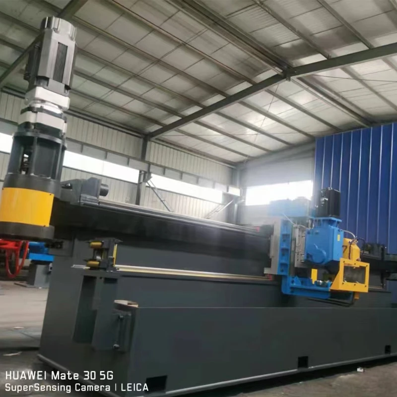
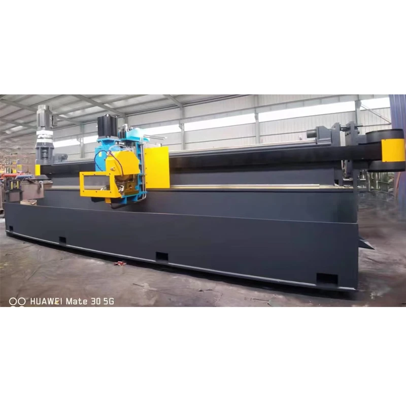
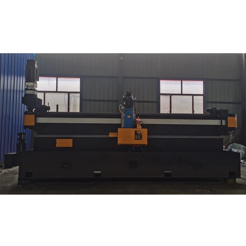
•Production speed: 10-140 meters/
•Saw blade parameters: Saw blade size: Φ 350x2.8x100 (high-speed steel saw blades are used for 1.5-2.2mm, alloy saw blades are used for 2.2mm and above), maximum noise ≤ 85 decibels.
•Production line feeding direction: left
•Installation plane to rolling bottom line height of 750 mm
•Walking motor 22Kw, feed motor 4.4Kw, sawing motor 7.5Kw, brand: Yaskawa
•Linear guide rail: 55 type, brand: Taiwan Shangyin
•Synchronous belt: SH 120RPP14-12000, ZHW 21F2042K, brand: German horse brand
•Bed structure: welded, normalized.
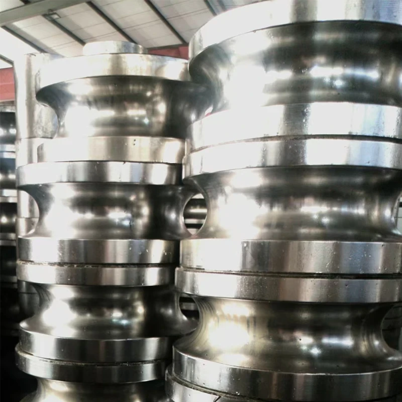
•Clamping form: hydraulic, fixture material Cr12, quenching hardness 60 °.
•Unit positioning method: Bottom line positioning.
•Cooling method: Water cooling, borrowing production water.
•Lubrication: Automatic lubrication, oil shortage alarm.
•Cutting steel pipe material: Q195/Q235/Q355
•Product range:
Round tube: diameter range 48mm, thickness range 2.0-3.5mm, fixed length 4-12000mm
•Installation plane to rolling bottom line height of 750 mm
•Saw blade size: Ø 400x2.8x120, maximum noise ≤ 85 decibels.
•Production speed is 15-120m/min.
•Walking motor 30KW, feed motor 4.4KW, sawing motor 11KW, brand: Yaskawa
•Linear guide rail: 55 type, brand: Taiwan Shangyin
•Synchronous belt: SH 150RPP14-135000 ZHW 21F2042K, brand: German horse brand
•Bed structure: welded, normalized.
•Clamping form: hydraulic, fixture material Cr12, quenching hardness 60 °. (Two sets of clamping assemblies are provided due to the difference in saw blade diameter)
•Unit positioning method: Bottom line positioning.
•Cooling method: Water cooling, borrowing production water.
•Lubrication: Automatic lubrication, oil shortage alarm.
Cutting steel pipe material: Q195/Q235/Q355
Product Range: Round Tube: Diameter Range 60mm, Thickness Range 2.0-3.75mm
Maximum production line speed: (Q195-355 material, saw blade parameters)
120 m/min (pipe diameter 60 mm, wall thickness 2.0-3.75mm, fixed length 4-12000mm)
•Installation plane to rolling bottom line height of 750 mm
•Saw blade size: Ø 400x2.8x120, maximum noise ≤ 85 decibels.
•Production speed is 15-100m/min.
•Walking motor 37Kw, feed motor 4.4Kw, sawing motor 15Kw, brand: Yaskawa
•Linear guide rail: 55 type, brand: Taiwan Shangyin
•Synchronous belt: SH 150RPP14-135000 ZHW 21F2042K, brand: German horse brand
•Bed structure: welded, normalized.
•Clamping form: hydraulic, fixture material Cr12, quenching hardness 60 °. (Two sets of clamping assemblies are provided due to the difference in saw blade diameter)
•Unit positioning method: Bottom line positioning.
•Cooling method: Water cooling, borrowing production water.
•Lubrication: Automatic lubrication, oil shortage alarm.
1.2 Sawing steel pipe length: 4000-12000mm
1.3 Length tolerance: ± 2 mm (requires production line speed fluctuation not to exceed 2%)
1.4 Post cutting burr height: Max: 0 2 mm
Main supporting manufacturers:
Servo motor: Yaskawa, Japan
Bearings: Ha, Wa, Luo Bearing Factory
Hydraulic components: Taiwan Oilfield
Electrical components:
1. The human-machine interface adopts a 10 inch touch screen, which can display the operating parameters and adjustment parameters of the flying saw. The brand is Weilun Tong.
2. Computer: self-developed
3. Encoder brand: Omron: VOLTS.5VDC-2000P/R, manufactured in Shanghai
4. Electrical components: Schneider, cables: Beijing Kunlun, cold pressed terminals: Zhejiang Kesi
5. One control cabinet and one operation console each
Equipment composition:
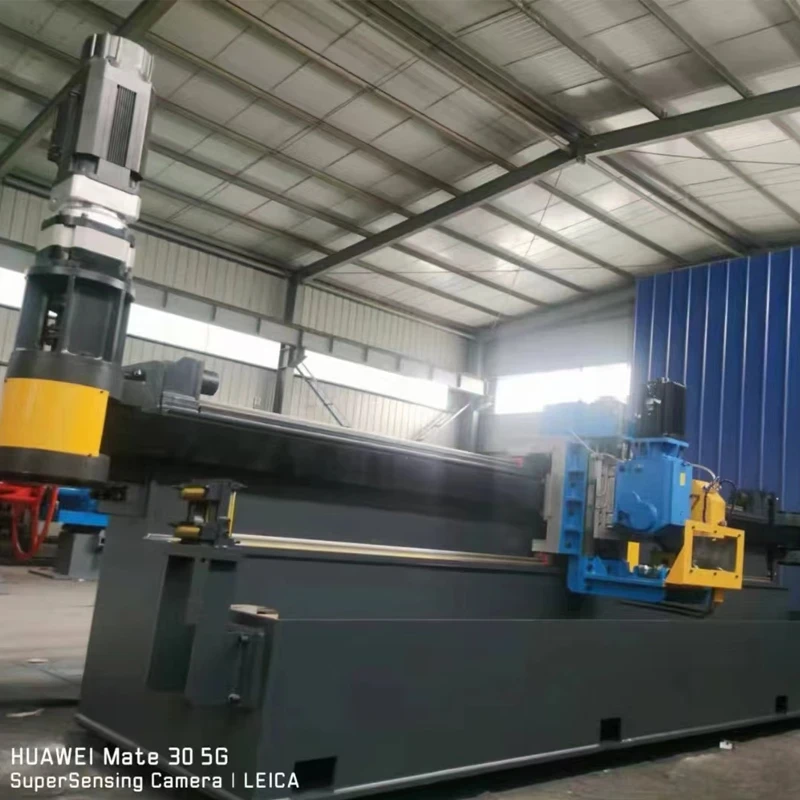
Two parts: dragging part and sawing head part
a) The dragging part includes: main dragging equipment, bed frame, lubrication system, hydraulic station, drag chain, electrical control equipment, operation console, servo system.
b) The saw head part includes: saw head, fixture, guide roller.
A) Dragging part: The movable saw carriage is supported on the bed by a linear guide rail, and is driven by a servo motor through a reducer and a toothed belt to move the carriage. The saw head, fixture, roller, etc. are installed on the carriage, and the fixture is driven by hydraulic pressure. It is divided into two groups and arranged in front and behind the milling head, with each group consisting of two vertical and horizontal fixtures. The guide rollers are also arranged in front of the sawing head and at one end of the bed, consisting of horizontal rollers and side guide rollers.
The horizontal rollers can be adjusted up and down, and the side guide rollers can be adjusted left and right to meet the requirements of steel pipe positioning. The drag electrical control adopts an imported high-power servo system as the tracking execution unit, an imported dedicated motion controller with high-performance microprocessor for tracking control, and a touch screen for parameter setting, display, and peripheral management. The electrical components are made of Schneider products or other well-known domestic brands.
B) Saw head section: used to complete the cutting of steel pipes. The sawing mechanism is as follows: the saw blade is driven by a servo motor through a hard toothed reducer, and the feed is achieved through the servo motor and ball screw.
2.2 The equipment base is equipped with an entrance guide roller, the saw blade on the trolley is equipped with a guide roller, and the fixture is equipped with a support roller;
2.3 The saw blade is equipped with a wire brush device that can be locked/removed for cleaning, making it easy to adjust and remove iron filings from the saw blade during rotation;
2.4 The spindle is equipped with a saw blade buffer device, which can reduce saw blade vibration and extend saw blade life
2.5 adopts imported linear guide rails, equipped with small car safety buffers on both sides, with a total of 2 pieces/set of flying saws;
2.6 Fixture clamping (hydraulic) mechanism:
2.6.1 Use two sets of clamping devices (hydraulic clutch);
2.6.2 The clamp block needs to be marked with specifications and markings;
2.6.3 The clamping block adopts a copper sleeve structure;
2.6.4 Equipped with adjustable cooling spray pipeline to flush impurities and iron filings on the saw blade and clamp block
All pipelines in mechanical equipment shall meet the following requirements:
·The tank drag chain is wide enough to ensure sufficient space inside;
·There are multiple isolation strips inside the tank drag chain, separating oil pipes, line pipes, water pipes, etc;
2.6.7 The layout of equipment anchor bolts is shown in the attached diagram, and each equipment is randomly equipped with a set of matching anchor bolts
Related News


