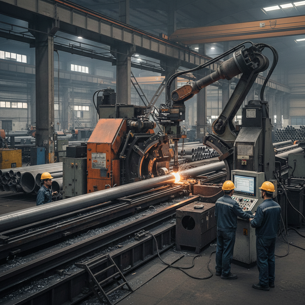
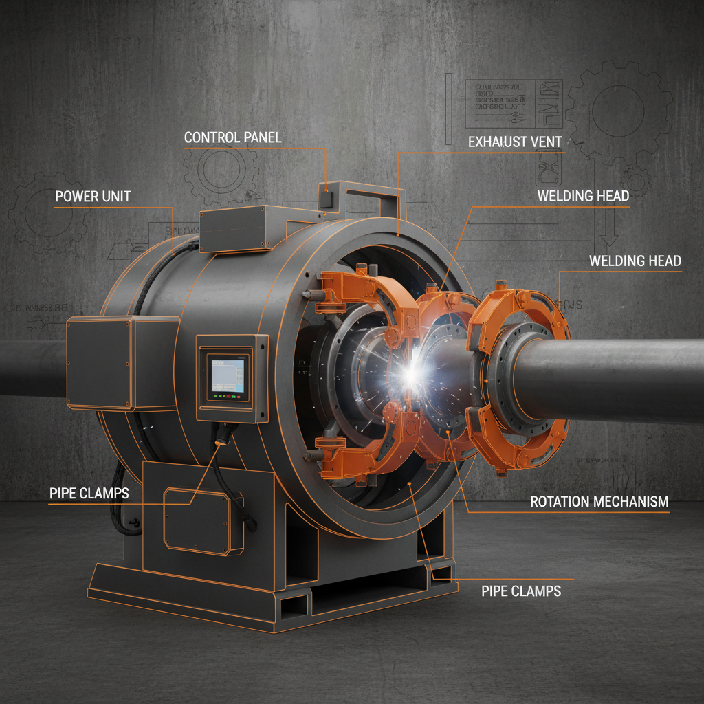
A welded steel pipe production line is a critical industrial asset for manufacturers in the metal forming and machinery sector, designed to transform flat steel strips into high-precision tubular structures. By combining mechanical forming with specialized welding processes, these lines enable the mass production of pipes used in everything from structural construction to fluid transportation, ensuring that material strength is maintained while maximizing throughput.
For many operators, the primary challenge lies in balancing production speed with dimensional accuracy and weld integrity. Inconsistent strip feeding, improper roller alignment, or inefficient cutting cycles can lead to significant material waste and increased labor costs, which directly impact the overall profitability of a pipe mill.
This analysis provides a comprehensive technical overview of the production process, detailing the core components from uncoiling to final straightening, and offering a framework for evaluating equipment specifications to ensure optimal operational efficiency.

Core Workflow of a Welded Steel Pipe Line

The operational flow of a welded steel pipe production line begins with the precise feeding of strip steel. The material, typically graded between Q195 and Q345, is uncoiled and leveled to remove internal stresses before entering the forming section. This sequence is vital because any residual curvature in the raw strip can lead to misalignment in the final pipe diameter.
Following the leveling phase, the steel passes through a series of forming and sizing rollers. The strip is gradually bent into a cylindrical shape and then fused using a welding process. The final stages involve cooling, cutting to specific lengths, and straightening to ensure the pipe meets industrial tolerances for linear accuracy.
Essential Auxiliary Machine Composition
Auxiliary equipment ensures the main forming unit operates without interruption. A critical component is the single-station manual uncoiler, which must adapt to various inner diameters (e.g., Ф762mm) and outer diameters (up to Ф1800mm). This ensures a steady supply of strip steel, supporting coils up to 5 tons to minimize downtime during material changes.
Additionally, the cage looper plays a pivotal role in buffering raw materials. By storing a calculated length of steel strip between the uncoiler and the sizing machine, it allows the production line to maintain a continuous flow even if the feeding section requires brief adjustments. Other essential tools include hydraulic cutting systems and pneumatic pressing platforms that prepare the strip for the welding phase.
Main Machine Technical Architecture
The heart of the welded steel pipe production line is the forming and sizing unit. For pipes in the φ76–φ89mm range, the architecture typically employs a passive seven-roller leveling system followed by a complex arrangement of forming rollers (such as 7 flat and 8 vertical rollers) and sizing rollers (6 flat and 6 vertical). This multi-stage process ensures the pipe achieves the exact wall thickness and diameter required.
Technical durability is achieved through the use of high-grade materials. Horizontal shafts (Ф100mm) and vertical roller shafts (Ф60mm) are typically manufactured from 40Cr steel, which is quenched and tempered to resist wear under high pressure. The transmission is often handled by spiral bevel gears in a ZG35# gearbox, providing the torque necessary to maintain speeds of 60-80m/min.
Analyzing Production Speed vs. Precision
Achieving a high forming speed without sacrificing length accuracy is a primary engineering goal. While the production line can operate at 60-80m/min, the precision of the final cut (often within ±3 mm) depends heavily on the synchronization between the drive motor and the cutting system. The following relative index illustrates how different technical factors impact the overall output quality of the system.
As shown in this conceptual framework, the synchronization of the speed measurement system and the stability of the DC motor (such as the 250KW Z4-280-42) are the most influential factors in maintaining consistency. When these parameters are optimized, the production line can reach its maximum sawing frequency of 15 times per minute without compromising the ±3 mm length accuracy.
The Role of Computerized Flying Saw Systems
The computer flying saw machine is essential for high-speed production because it eliminates the need to stop the line for cutting. By utilizing a saw car that travels in tandem with the moving pipe, the system can execute precise cuts at speeds up to 80m/min. This mechanism consists of a bed, gear-rack box, and a high-speed AC sawing motor (55KW) combined with a DC driving motor (22KW).
Accuracy in this stage is maintained via an integrated speed measurement system and air pressure controls (5-7Kg/cm²). For pipes with a wall thickness of 2-5mm, the flying saw ensures that fixed lengths of 4-8m are achieved with minimal material scrap, which is critical for maintaining the cost-efficiency of the manufacturing process.
Stress Relief and Straightening Processes
Post-welding, steel pipes often exhibit internal stresses and slight bending, which must be corrected to meet structural standards. The straightening machine employs a four-column frame structure with a specific roller configuration: four upper passive rollers and two lower active rollers. By applying pressure via a worm gear, the machine eliminates deviations in the pipe's linearity.
The efficiency of this process is determined by the straightening speed (up to 100m/min) and the material of the rollers. Using GCr15 steel with a hardness of HRC60-65 for the main rollers ensures that the machine can handle pipes from φ60 to φ89mm without excessive wear, maintaining a 30° angle between the roller and the pipe for optimal stress redistribution.
Equipment Specification Selection Framework
When configuring a welded steel pipe production line, the choice of components should be driven by the intended pipe specifications and the required production volume. Selecting the wrong motor capacity or roller material can lead to premature equipment failure or substandard pipe quality. The table below provides a qualitative comparison of different configuration approaches.
| Approach | Key Driver | Best Use Case | Primary Risk |
|---|---|---|---|
| Manual Setup | Low Initial Cost | Small Batch/Custom | High Labor Cost |
| Semi-Automated | Balanced Throughput | Medium Scale Prod. | Moderate Downtime |
| Fully Automated | Maximum Efficiency | High Volume Industrial | High Initial Capex |
| Precision-Focused | Tight Tolerances | High-Spec Engineering | Slower Line Speed |
| Speed-Focused | Massive Output | Standard Construction | Higher Scrap Rate |
| Modular Design | Flexibility | Diverse Product Mix | Complex Integration |
Ultimately, the integration of components—from the uncoiler to the roller table—must be seamless. For enterprises operating in the metal forming industry, focusing on the synergy between the DC drive systems and the computerized sawing mechanisms is the most effective way to ensure a high ROI on the production line investment.
Frequently Asked Questions
These production lines are typically designed for strip steel grades such as Q195 and Q345, which provide the necessary balance of weldability and structural strength for industrial pipes.
The cage looper acts as a buffer that stores raw material, ensuring the forming and sizing machines can operate continuously even during minor fluctuations in the feeding speed from the uncoiler.
Length accuracy is primarily determined by the synchronization between the line's speed measurement system and the computer flying saw machine's driving motor.
The forming and welding processes introduce thermal and mechanical stresses that can cause the pipe to bend; straightening eliminates these deviations to ensure linear precision.
High-wear components like roller shafts are typically made from 40Cr steel (quenched and tempered) or GCr15 for straightening rollers to maintain hardness and longevity.
Yes, production lines can be adapted by changing the roller molds and adjusting the forming unit arrangement to accommodate different diameter and wall thickness specifications.
Conclusion
The efficiency of a welded steel pipe production line depends on the precise integration of its auxiliary and main components. By prioritizing high-grade materials for rollers and implementing synchronized computerized cutting and straightening systems, manufacturers can achieve high throughput while maintaining strict dimensional tolerances. The transition from manual feeding to automated, buffered systems is the key to reducing labor intensity and increasing overall plant productivity.
For enterprises evaluating implementation options or seeking specific technical configurations, detailed product information and customized solutions are available at www.xhequipment.com to help optimize your manufacturing capacity.